
Electromagnetic induction surveys
Jouni Lerssi, Geological Survey of Finland, PO Box 1237, 70211 Kuopio, Finland; jouni.lerssi@gtk.fi
Description
Electromagnetic induction (EM), as the name implies, uses the principle of induction to measure the electrical conductivity of the subsurface. A primary alternating electric current of known frequency and magnitude is passed through a sending coil creating a primary magnetic field in the space surrounding the
coil, including underground. The eddy currents generated in the ground in turn induce a secondary current in underground conductors which results in a alternating secondary magnetic field, that is sensed by the receiving coil. The secondary field is distinguished from the primary field by a phase lag. The ratio of the magnitudes of the primary and secondary currents is proportional to the terrain conductivity. The depth of penetration is governed by the coil separation and orientation. Unlike conventional resistivity techniques, no ground contact is required. This eliminates direct electrical coupling problems and allows much more rapid data acquisition.
Some EM induction equipments
For shallow profiling (up to 6 m), a Geonics, Inc. EM-31 Terrain Conductivity meter can be used. One person can collect as many as 10,000 data points per day with this instrument. An EM-34 is used for depths of investigation between 9 and 50 m. This instrument requires two people to operate, and up to 500 data points per day can be collected under good conditions. These tools are extremely sensitive and accurate, capable of detecting variations in conductivity of as little as 3%. Data are automatically stored in an electronic data logger for later transfer to a computer.
The EM-61 instrument is a high resolution, time-domain device for detecting buried conductive objects. It consists of a powerful transmitter that generates a pulsed primary magnetic field when its coils are energized, which induces eddy currents in nearby conductive objects. The decay of the eddy currents, following the input pulse, is measured by the coils, which in turn serve as receiver coils. The decay rate is measured for two coils, mounted concentrically, one above the other. By making the measurements at a relatively long time interval (measured in milliseconds) after termination of the primary pulse, the response is nearly independent of the electrical conductivity of the ground. Thus, the instrument is a super-sensitive metal detector. Due to its unique coil arrangement, the response curve is a single well defined positive peak directly over a buried conductive object. This facilitates quick and accurate location of targets. Conductive objects, to a depth of approximately 10 feet can be detected.

Fig.1 EM-61 (© Geonics, Inc.).
The EM 31 uses an alternating electromagnetic field, which fills the space, below and above ground, surrounding the transmitting coil. When the electromagnetic field couples with a conductor, for example a steel pipe under the ground, AC eddy currents are induced to flow in the pipe. This generates a secondary magnetic field, which is sensed by the co–planar (3,66 m offset) receiver coil. Due to phase lag the computer on board can discriminate between the primary and secondary fields and outputs the measurements of the secondary field (thus, a conductive zone is sensed by the induced secondary magnetic field).

Fig.2 EM-61 (© Geonics, Inc.).
Electromagnetic induction (EMI) instruments provide a rapid assessment of the soil’s electrical conductivity. They can provide information that can be used for land resource assessment, salinity assessment, soil works, precision farming and property and catchment management.
The technology works on the basis that within an electromagnetic field, any conductive body carries a current. The instrument measures the apparent flow of electrical conductivity through the soil, called the soil’s apparent electrical conductivity (ECa) measured in milliSiemens / metre, (mS/m). Each instrument has two coils (a transmitter and a receiver) that are at a fixed (EM38, EM31 and EM39) or a variable (EM34) separation. The instrument induces an electrical current into the soil, with the depth of penetration determined by the separation of the coils and the frequency of the current. ECa is affected by the soil’s salt content and type, clay content and type, mineralogy, depth to bedrock, soil moisture, organic matter and temperature.
The 4 most common types of EMI instruments, are the EM38, EM31, EM34 and EM39. Although they all operate the same, they vary in the depth to which they read within the soil profile. All operate in both the vertical and horizontal mode (this determines the depth to which they read). A summary of this is given below:
- EM38 – vertical mode (1.5m) horizontal mode (0.7m)
- EM31 – vertical mode (6.0m) horizontal mode (3.0m)
- EM34 – 6.0m to 60.0m
- EM39 – used for logging down boreholes.
These depths are only indicative, as the depth of penetration of the electrical signal will be determined by the uniformity, or non-uniformity, of the soil. If the soil is very conductive near the surface then the signal will be dissipated and will not read to a greater depth.
Soil data is required to validate the EMI survey. Soil sampling sites need to be selected to represent the range of soil conductivity zones (low, medium and high) based on the range of ECa values as collected by the EMI instrument. Samples need to be collected to a depth that is indicative of the machines capability. If validating an EM31 survey, then it is necessary to sample to a depth of 6.0 metres. Soil samples need to be tested for a range of parameters depending on what the data is being collected for.
Most traditional EMI sensors have separate TX and RX coils connected by cables. This is due to the notion that the TX-RX separation ultimately governs the depth of exploration: the farther they are separated, the deeper we can see.
The most recent entry in this field is a new generation of one-man portable, digital, broadband EMI sensors developed by Geophex: the GEM-2 has a separation of 1.66 m between the transmitter (TX) and receiver (RX). The sensors has a 30-Hz data rate at typical 3-10 simultaneous frequencies and, currently, a bandwidth of 30 Hz to 96 kHz, a span of about three decades; the receiving coil measures the induced secondary fields. Sensor weighs about 4 kg and comes in a single handheld package. In low-conductivity soils (such as dry sands) the lower-frequency electromagnetic (EM) fields penetrate several meters into the subsurface, while at higher frequencies the instrument investigates shallower depths. The system operates by transmitting a composite waveform of electromagnetic energy into the ground. The primary incentive for such small sensors is obvious: portability and speed.


Fig 3. GEM-2 (© Geophex, Ltd. and Jouni Lerssi (GTK)).
The Profiler EMP-400 is GSSI’s electromagnetic induction tool very similar to GEM-2. This EM product was built from the ground up using a proprietary source cancellation and calibration system to create the big signal stability.
Profiler’s system structure, electronics and coils are designed for maximum structural and thermal stability. These key features minimize signal drift and maintain an accurate zero level and system null across the full bandwidth of the system, whereas signal drift is a common problem with other EM instruments. These older instruments, which do not incorporate the advanced electronics and software control employed in the Profiler, produce data with significant problems that cause inaccurate results.
Features of the Profiler EMP-400
- Coil Spacing 1.21 m (4 ft)
- Operational Bandwidth1 kHz to 16 kHz
- Memory 248.5 MB
- 180,000 continuous data points
- 360,000 discrete data points
- PowerRe-chargeable Lithium Ion battery or 8 (eight) AA batteries
- Data TransferVia Microsoft® Active Sync
- Display 5.58 x 7.36 cm (2.2 x 2.9 in) color screenRecords 1 to 3 frequencies
- Measurement values:
- In-phase: PPM
- Quadrature: PPM
- Conductivity: mS/m
- Mechanical Dimensions1.46 m (L) x 24 cm (W) x 12.4 cm (H)
57.5″ x 9.5″ x 4.9″Weight4.535 kg, (9.9 lbs) - Environmental Water Resistant
Typical Uses of the GEM-2 and Profiler EMP-400 include:
- Environmental remediation
- Archaeology
- Geological investigation
- Site assessment
- Ground water investigation
- Agricultural research
The advantage of the GEM-2 and Profiler EMP-400 over Direct Current (DC) systems (eg. OhmMapper or the SuperSting) is that its ski design, held by a shoulder strap, provides greater flexibility for investigating anomalies in dense vegetation and often allows more rapid data acquisition. A disadvantage is its lower resolution compared to DC-resistivity soundings.
Appropriate applications
- Mineral exploration – metallic elements are found in highly conductive massive sulfide ore bodies.
- Groundwater investigations – groundwater contaminants such as salts and acids significantly increase the groundwater conductivity.
- Stratigraphy mapping – rock types may have different conductivities.
- Geothermal energy – geothermal alteration due to hot water increases the conductivity of the host rock.
- Permafrost mapping – there is a significant conductivity contrast at the interface between frozen and unfrozen ground.
- Environmental – locate hazards such as drums and tanks, contaminant plumes.
Performance
Advantages
- TDEM systems may be used in many different configurations.
- A pulsed transmitter waveform allows the receiver to measure the electromagnetic response during the transmitter off-time without the presence of the primary field.
- No direct electrical contact with the ground is required so that surveys can be equally effective in frozen environments.
- The same basic techniques can be used to investigate the top few meters of ground or to depths over 1000 meters.
- Generally fast and cost effective for the amount of data generated.
Limitations
- Do not work well for high resistive region.
- Susceptible to interference from nearby metal pipes, cables, fences, vehicles and induced noise from power lines.
- EM equipment tends to be somewhat more costly due to its greater complexity. Need more sophisticated interpretation skill.
- Not effective for very shallow measurements. Fixed depth of investigation depending on frequency used and Tx-Rx separation.
Design requirements
Basic principle of Electromagnetic induction measurement (Fig 4.)
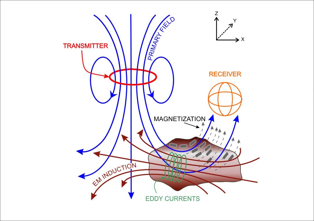
Fig. 4. Basic principle of Electromagnetic induction measurement (© Riitta Turunen, GTK).
GEM-2
The GEM-2 ski contains three coils: transmitter, bucking, and receiver coils. For frequency-domain operation, the GEM-2 prompts for a set of desired transmitter frequencies. Built-in software converts this into a digital “bit-stream,” which is used to construct the desired transmitter waveform (Figs 5 and 6). This bit-stream represents the instruction on how to generate a complex waveform that contains all frequencies specified by the operator.

Figure 5. A three-frequency transmitter waveform.
Figure 6. First 33 points of Figure 5.

Figure 7. The base period of the bit-stream for the GEM-2 is set to 1/30th of a second for areas having a 60-Hz power. The TX switches at 192 kHz and, therefore, the bit-stream contains 6,400 steps within the period. Through a Fourier transform of the transmitter current waveform above, we obtain a power spectrum of the primary field, which shows each transmitted frequency.
Figure 8. With multiple frequencies, one can determine layered conductivity structure of the earth, conceptually shown below. This is called “frequency sounding” method. For further discussion, read and article entitled, “Apparent Conductivity (or Resistivity) Revisited” by I.J. Won.
Figures 5 – 8 © Geophex, Ltd.
References
Geonics, Inc.: EM-61 and EM-31 brochures (© Geonics, Inc.).
Geophex, Ltd: GEM-2, hand-held, digital, multi-frequency broadband electromagnetic sensor (© Geophex, Ltd.).
Geophysical Survey Systems, Inc. (GSSI): The Profiler EMP-400 , multi-frequency electromagnetic sensor (© GSSI, Inc.).
Reynolds, J.M. 2011. An Introduction to Applied and Environmental Geophysics. John Wiley & So n s Ltd, Chichester, 2nd ed.,712 pp.
David M. Nielsen, ed., 2006: Practical handbook of environmental site characterization and ground-water monitoring, second edition, CRC Press, pp. 249-295.