
Aerobic constructed wetlands
Introduction
In general, constructed wetlands have some type of a barrier of impervious sediment or synthetic liner to prevent seepage, engineered structures to control flow direction, hydraulic retention time and water level and soil to support the roots of the emergent vegetation. The two basic types of constructed wetlands in common use are free water surface (FWS) flow wetlands and subsurface flow (SSF) wetlands which can be divided further to horizontal flow (HF) wetlands and vertical flow (VF) wetlands. Aerobic, subsurface VF wetland systems are also known as reed beds or infiltration wetlands. In FWS the water surface is exposed to the atmosphere, whereas in SSF the water level is maintained below the surface of gravel or other media placed in the wetland bed. Constructed aerobic wetlands (Fig. 1) are based on aeration of the water to be treated, resulting in transformation of dissolved Fe to the solid phase via oxidation. Thus, aerobic wetland treatment is very effective in treating Iron-rich mine waters, yet they commonly have limited capability to neutralize acidity. (Wildeman et al. 1993, Brix 1994, Cooper 1999, Sundaravadivel & Vigneswaran 2001).
Performance
Due to extensive water surface and slow flow, aerobic wetlands promote metal oxidation and hydrolysis resulting in precipitation of iron, aluminium and manganese into metal hydroxide forms. The precipitation of metal hydroxides may also enhance co-precipitation of several ionic species such as arsenic and molybdenium. The precipitates are retained in the wetland or downstream. Metal removal may also be carried out by ion exchange and organic complexation. In addition, small scale metal removal is carried out by iron plaque formation on roots and rhizomes of wetland macrophytes through oxygenation of the rhizosphere. According to several studies (e.g. Hedin et al. 1994, Watzlaf et al. 2004, Younger et al. 2004) typical removal rates of aerobic wetlands are 10 to 20 g/d/m2 for iron, and 0.5 to 1.0 g/d/m2 for manganese. Aerobic wetlands may be used also in reducing biological oxygen demand, coliform bacteria and cyanide/cyanate oxidation. (e.g. Wolkersdorfer 2008, Gusek & Figueroa 2009).


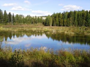
Figure 1. Constructed wetland at Luikonlahti Cu-Zn-Co-Ni mine in Finland, a) and c) during construction phase in 2007, b) in spring 2013 and d) in july 2013. (Photos a) © M.L. Räisänen, 2007 b) © GTK, 2013, c) © A. Tornivaara, 2007 and d) © K. Turunen, 2014)
Aerobic wetlands are relatively shallow, either constructed or natural ponds that are filled with flooded gravel, soil and organic substrate for plant growth. The cells are usually 30 cm deep or less, lined with impermeable sediments and water flows above the substrate. The shallow water level in individual wetland cells is maintained by piping and hydraulic controls to allow aeration of the water to be treated. Aeration may be further enhanced by cascades, riffles or falls between individual cells. Overall, the higher the iron content of the water, the more aeration steps are needed. FWS wetlands typically consist of a basin or channel with an impervious liner to prevent seepage, substrate media to support the vegetation, and water flow above the substrate in a horizontal direction (Figure 2). The biological activity generally takes place in the surface layer of the soil and in water. (e.g. Wolkersdorfer 2008, Gusek & Figueroa 2009, Wendling & Mroueh 2013).
SSF wetlands also consist of a basin or channel with an impervious liner, but the water level is maintained below the bed surface of porous solid media. Rock and gravel are the most commonly used media, which also support the root structure of emergent vegetation. Selection of suitable substrate with adequate permeability is essential, as selection of a poorly-suited or inadequately researched substrate at application scale can lead to failure of the system. (Felde & Kunst 1997, Laber et al. 1997).
In HF wetlands, the substrate is completely saturated with a continuous flow of influent water (Figure 3), whereas the VF wetland systems (Figure 4) are generally operated with intermittent water to enhance the oxygen supply to achieve full nitrification. The aeration in VF wetlands may be promoted by pipes positioned within the substrate (Felde &Kunst 1997, Laber et al. 1997). If VF wetlands are constructed as a single stage or with multiple stages the influent can be diverted from one stage to the next as required to maintain unsaturated conditions in each unit. A disadvantage of VF wetland systems is that their substrate is prone to clogging, and substrate replacement if often expensive. In addition, the intermittent water flow often requires pumping and VF wetlands often rely on controlled source of energy and are thus less passive than other systems. In contrast, in HF wetlands the water flows by gravity without need for pumping or external energy. (Blazejewski & Blazejewska 1997, Kayser & Kunst 2005).

Figure 2. Free water surface wetland. (Modified from Wildeman et al. 1993, Kadlec & Wallace 2008, © GTK 2014)

Figure 3. Horisontal flow wetland. (Modified from Wallace & Knight 2006, Vymazal 2010, © GTK 2014)

Figure 4. Vertical flow wetland. (Modified from Vymazal 2010, © GTK 2014)
The porous rock or gravel media of SSF wetland provides longer hydraulic retention time, greater available surface area and contact between the waste water and substrate than a similarly sized FWS wetland. This may increase the rate and extent of contaminant removal and as the treatment responds faster in SSF wetland than in FWS wetlands, the area can be designed smaller (Davies & Cottingham 1993). In addition, by maintaining the water level below the solid surface it limits the risk of odour, human or wildlife exposure to waste waters, or insect vectors. The subsurface position of the water and the accumulated plant debris on the surface of the SSF bed offer greater thermal protection in cold climates than the FWS type. (e.g. Davies & Cottingham 1993, Felde & Kunst 1997, Laber et al. 1997).
In general, mine waters are not adequately treated in single stage wetland systems (Vymazal 2005) and the most effective constructed wetland system is most likely a hybrid wetland with integrated units using a combination of flow and bed types (Wood 1995). Hybrid wetland systems consist of a combination of surface and subsurface systems incorporating either or both VF and HF beds combined to complement the advantages and disadvantages of each (Cooper 1999, Vymazal 2005). For instance, FWS wetlands may be an effective component of a hybrid wetland system in the N removal processes (e.g. nitrification) and in reducing potential for system clogging via pre-treatment and particulate removal from influent wastewater prior to flow through HF or VF wetland beds. On the other hand, VF wetlands are considered effective for nitrification, as they have a high oxygen transfer rate, which leads to good removal of biological and chemical oxygen demand (BOD and COD, respectively). Comparatively, subsurface HF wetland systems exhibit effective removal of suspended solids, as well as denitrification (Cooper 1999).
Design requirements
Constructed aerobic wetlands are based on aeration of the water to be treated, resulting in the transmformaiton of dissolved Fe to the solid phase via oxidation. Thus, aerobic wetland treatment is very effective in treating Iron-rich mine waters, yet they have commonly limited capability to neutralize acidity. In addition, commonly accompanying manganese requires specific conditions for removal: circum-neutral to basic pH and Fe2+ must be oxidized to prevent manganese from reducing. The pH influences both solubility of metal hydroxide precipitates and the kinetics of hydrolysis and oxidation. Since hydrolysis is a net acid-generating process, mine water has to be net alkaline (KA4.3≥KB8.2, pH>5.5) so that despite of the decreased pH the alkalinity of the water will buffer the acidity and metal precipitation continues. The acidity may be amended by anoxic limestone drain (ALD) treatment. In addition CO2 should be stripped off and O2 enhanced by cascades, riffles or falls before introducing the water into the wetland. (Wolkersdorfer 2008, Gusek & Figueora 2009)
Regardless of the flow orientation, it is commonly agreed that planted wetlands generally outperform unplanted ones (Gagnon et al. 2007). Properly planted vegetation assist in aeration of the substrate and promotes uniform flow condition by reducing the velocity and preventing formation of shortcuts (unless planted in straight lines). This increases the residence time and enhances microbially catalysed oxidation, precipitation and co-precipitation in the wetland. Aerobic wetlands are commonly planted with plants and/or oxidizing bacteria to enhance the treatment processes. Plants such as Common reed (Phragmites australis), Common rush (Juncus effuses) or Reedmace (Typha latifolia) have the ability to take up metal such that wetland treatment can also be considered a phytoremediation method. Common bacterias used are Thiobacillus ferrooxidans, Leptothrix discophora and Ulothrix. In some cases, the role of wetland vegetation and rhizospheral processes on metal mobility or retention may also be significant. Plants may enhance the metal removal by physical filtration of colloidal metal hydroxides or direct uptake from solution by shoots, roots and fibrous wetland materials. However, the vegetation mainly enhances physical filtration of suspended metal particles and colloids and the direct metal up take by plants is often negligible. In addition the capacity of the plants to remove metals is soon exhausted as absorption sites are filled. (Wolkersdorfer 2008, Gusek & Figueroa 2009)
Sizing
The removal efficiency of a treatment wetland can be calculated from the changes in contamination concentrations of inflow and outflow with the following equation (e.g. Younger et al. 2002):
Removal efficiency (%) = 100 [(Cin – Cout)/(Cin)]
where, Cin = concentration of inflow (mg L-1)
Cout= concentration outflow (mg L-1)
However, although the previous equation can be used when estimating single system, it does not consider information about element loadings, inflow or the dimensions of the system. Hence, outcomes are relative and therefore cannot be used for comparison to other treatment facilities. Thus it is suggested that removal efficiency equations should be adjusted related to area and flow. A common method to consider flow aspect is to use loadings in place of concentrations. Consequently the area-adjusted contaminant removal (RA) can be calculated with the following equation (Younger et al. 2002):
RA = (Qin*Cin – Qout*Cout)/A
where, A = the wetland area (m2)
Qin = the average daily inflow (m3d-1)
Qout = the average daily outflow (m3d-1)
Once the RA is estimated, the sizing of a treatment wetland can be designed based on the following model (Younger et al. 2002):
A = Qin (ln Cin – ln Cr)/ RA
where, A = the required wetland area (m2)
Cr = the required concentration for this contaminant after treatment (mg L-1)
Appropriate applications
In comparison to other passive water treatment technologies, constructed wetlands are fairly cost-effective, long-term systems and the changes in flow rates are easily controlled due to large storage volumes. Wetlands also often function as a tool for wildlife and landscape rehabilitation. However, they often require large areas for construction. Freezing is a significant constraint on aerobic wetlands and the treatment efficiency may drop during the winter. However, some plant/algae species can function below the ice or snow cover and thus the design of the vegetation for the wetland should mimic the local ecosystem. Constructing the cell system with variable water depths and with diversified plant community helps the wetland to remain functional through periods of stress. Also, in cold climates fluctuation of flow (e.g. during spring snow melt) may hinder the efficiency of the wetland treatment due to elevated flow rates. Thus, wetland treatment has a limited period of effective time in colder climates. However, the subsurface position of the water and the accumulated plant debris on the surface of the SSF wetland bed also increase thermal protection in cold climates. (Wolkersdorfer 2008, Gusek & Figueroa 2009)
Table 1. The functionality of the different types of constructed aerobic wetlands.
| Wetland type | Effluent quality | Removal efficiency | Advantages | Disadvantages | References |
| Aerobic free water surface (FWS) wetlands | Neutral or net alkaline drainage, best for pH >5.5 | High reduction in BOD and suspended solids. | Simple design, low cost, storage of precipitates. Little maintenance needed. Ecological, landscape and wildlife rehabilitation value. | Large surface area. In acidic conditions, plants may not survive, oxidation rates may decrease, and system may fail. | Hedin et al. 1994, Taylor et al. 2005 |
| Vertical flow (VF) subsurface wetland | Neutral or net alkaline drainage. | High reduction in BOD, suspended solids Fe and N. | Simple and smaller in area compared to FWS wetland. Better thermal protection due to substrate, subsurface position of the water and accumulation of plant debris. | Prone to substrate clogging, resulting reduced efficiency and need for costly replacement of substrate. In acidic conditions, plants may not survive, oxidation rates may decrease, and system may fail. Dosing system requires more complex engine. | Brix 1994, Davies et al. 1993, Felde & Kunst 1997, Sundaravadivel & Vigneswaran 2001, Cooper 1999, Taylor et al. 2005. |
| Aerobic horizontal flow (HF) subsurface wetland | Neutral or net alkaline drainage. | High reduction in BOD, suspended solids and effective denitrification. | Simple and smaller in area compared to FWS wetland. Better thermal protection due to substrate, subsurface position of the water and accumulation of plant debris. | In acidic conditions, plants may not survive, oxidation rates may decrease, and system may fail. Prone to substrate clogging, resulting reduced efficiency and need for costly replacement of substrate. | Cooper 1999, Davies & Cottingham 1993, Vymazal 2005, Taylor et al. 2005. |
Case examples of mine sites with aerobic wetlands in Finland:
- The removal of metals and sulphate in a constructed passive system (combined system of aerobic and anaerobic wetlands and OLD) at Cu-Zn-Co-Ni Luikonlahti mine in Eastern Finland.
- Wetland treatment in the former settling pond at the Enonkoski mine site.
- Wetland treatment in the former settling pond at the Vihanti mine site.
References
Blazejewski, R. & Blazejewska, S.M. 1997. Soil clogging phenomena in constructed wetlands with subsurface flow. Water Science and Technology 35(5):183-188
Brix, H. 1994. Use of constructed wetlands in water pollution control: Historical development, present status, and future perspectives. Water Science and Technology 30(8):209-223.
Cooper, P. 1999. A review of the design and performance of vertical-flow and hybrid reed bed treatment systems. Water Science and Technology 40(3):1-9.
Davies, T. H. & Cottingham, P.D. 1993. Application of constructed wetlands to treat wastewaters in Australia. In: G. A. Moshiri (Ed.): Constructed Wetlands for Water Quality Improvement. Boca Raton, Florida, Lewis Publishers. Pp. 577-584.
Felde, K.V. & Kunst, S. 1997. N- and COD-removal in vertical-flow systems. Water Science and Technology 35(5):79-85.
Gagnon, V., Chazarenc, F., Comeau Y. & Brisson, J. 2007. Influence of macrophyte species on microbial density and activity in constructed wetlands. Water Science and Technology 56(3):249-254.
Gusek, J. & Figueroa, L. 2009. Mitigation of Metal Mining Influenced Water. Part 2. SME. 164 p.
Hedin, R.S., Nairn, R.W. & Kleinmann, R.L.P. 1994. Passive treatment of coal mine drainage, US Bureau of Mines Information Circular 9389 (2nd Ed.). Pittsburg. 35 pp.
Kadlec, R.H. & Wallace, S. 2008. Treatment wetlands, 2nd ed. Taylor & Francis group.Florida.
Kayser, K. & Kunst, S. 2005. Processes in vertical-flow reed beds: nitrification, oxygen transfer and soil clogging. Water Science and Technology 51(9):177-184.
Laber, J., Perfler, R. & Haberl, R. 1997. Two strategies for advanced nitrogen elimination in vertical flow constructed wetlands. Water Science and Technology 35(5):71-77.
Sundaravadivel, M. & Vigneswaran, S. 2001. Constructed wetlands for wastewater treatment. Critical Reviews in Environmental Science and Technology 31(4):351-409.
Taylor, J., Pape, S. & Murphy, N. 2005. A Summary of Passive and Active Treatment Technologies for Acid and Metalliferous Drainage (AMD). Proceedings of the fifth Australian Workshop on acid drainage 29th-31st August 2005, Fremantle, Australia. pp. 151-200.
Younger, P.L., Banwart, S.A. & Hedin, R.S. 2002. Mine water – Hydrology, Pollution, Remediation. Environmental pollution. Volume 5. Kluwer Academic Publisher, The Netherlands.464 p.
Vymazal, J. 2005. Horizontal sub-surface flow and hybrid constructed wetlands systems for wastewater treatment. Ecological Engineering 25(5):478-490.
Vymazal, J. 2010. Constructed Wetlands for Wastewater Treatment. Water, 2, 530-549.
Wallace, S. & Knight, R.L. 2006. Small Scale Constructed Wetland Treatment Systems: Feasibility, Design Criteria and O&M Requirements. Water Environment Research Foundation, 350 pages.
Watzlaf, G.R., Schroeder, K.T., Kleinman, R.K.L.P., Caries, C.L. & Nairn, R.W. 2004. The Passive Treatment of Coal Mine Drainage. US Department of Energy DOE/NETL- 2004/1202. Available from: www.netl.doe.gov.
Wildeman, T., Brodie, G. & Gusek, J. 1993. Wetlands Design for Mining Operations. BiTech Publishers Ltd.
Wendling, L. & Mroueh, U-M. 2013. Passive treatment of mine wastewaters using wetlands – case studies and application assessment. VTT Technology. (unpublished)
Wolkersdorfer, C. 2008. Water Management at Abandoned Flooded Underground Mines. Fundamentals, Tracer Tests, Modelling, Water Treatment. Springer. 465 p.
Wood, A. 1995. Constructed wetlands in water pollution control: Fundamentals to their understanding. Water Science and Technology 32(3):21-29.
Leave A Comment
You must be logged in to post a comment.